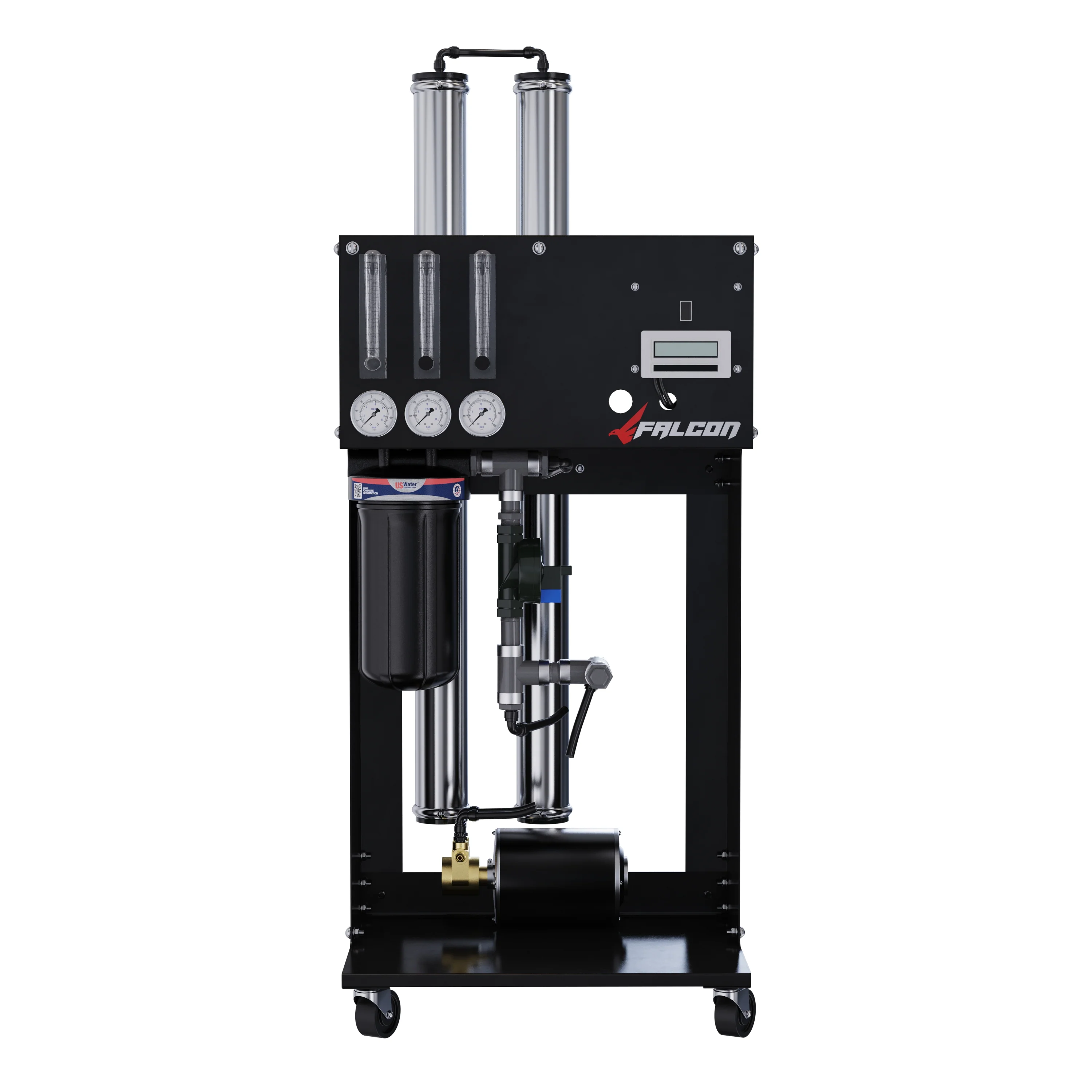
US Water Systems Falcon Commercial RO Review (2026): 500–2,000 GPD Skid-Mounted
Source: US Water Systems Falcon 220-FALM Product Manual • US Water Systems, Inc., Indianapolis, Indiana
FALM-500 through FALM-2000 • 98.5% salt rejection • Up to 75% recovery • 110V single-phase • Skid-mounted • Car detailing • Window washing • Food service • Greenhouse
Model Comparison — FALM-500 Through FALM-2000
| Spec | FALM-500 | FALM-1000 | FALM-1500 | FALM-2000 |
|---|---|---|---|---|
| Daily output (rated) | 500 GPD | 1,000 GPD | 1,500 GPD | 1,500 GPD |
| Permeate flow (GPM) | 0.35 | 0.69 | 1.04 | 1.38 |
| Membrane size | 2.5"×21" | 2.5"×21" | 2.5"×40" | 2.5"×40" |
| Membrane part | 255-T2521-450-XLE | 255-T2521-450-XLE | 255-T2540-900-XLE | 255-T2540-900-XLE |
| Standard recovery | 26% | 33% | 45% | 58% |
| Max recovery (recycle) | Up to 75% on all models | |||
| Concentrate to drain (standard) | 1.0 GPM | 1.38 GPM | 1.25 GPM | 1.0 GPM |
| Power | 110V / 60Hz / 1-Phase / 15-amp breaker (all models) | |||
| Salt rejection | 98.5% nominal (all models) | |||
| Test conditions: 550 ppm TDS, 5-micron filtered, dechlorinated, softened city feed water, 35 PSI feed, 150 PSI operating, 77°F, pH 7.0, 30-min stabilization. | ||||
Model Selection Guide
| If you need… | Choose | Why |
|---|---|---|
| Car detailing, window washing (1–2 operators) | FALM-500 | 500 GPD is ample for 1–2 professional detailers; lowest entry cost |
| Small restaurant, coffee shop, ice machine | FALM-1000 | 1,000 GPD covers most small food service daily demand |
| Greenhouse, light food processing | FALM-1500 | 1,500 GPD handles irrigation and light processing with headroom |
| Multi-operator car wash, medium restaurant, cleaning service | FALM-2000 | Maximum Falcon capacity; 75% recovery at 2,000 GPD is the sweet spot for water cost savings |
| >2,000 GPD requirement | Defender HD | Falcon tops out at 2,000 GPD; Defender starts at 2,000 and goes to 16,000 GPD |
The 75% Concentrate Recycle — What It Means and How to Set It
Standard commercial RO systems at this capacity tier recover 26–58% of feed water as permeate. The remaining 42–74% goes to drain as concentrate. At high throughput this represents real water and sewer cost. The Falcon’s concentrate recycle circuit routes a controlled portion of the concentrate back to the membrane inlet, reducing drain flow and boosting effective recovery to 75%.
Step 2: Total Flow = 1.39 ÷ 0.75 = 1.85 GPM
Step 3: Concentrate to drain = 1.85 − 1.39 = 0.46 GPM
Step 4: Recycle = Min flux (1.0 GPM for 2.5" membrane) − 0.46 = 0.54 GPM recycle
Pre-Treatment — Non-Negotiable Requirements
Pre-treatment is mandatory — not optional. US Water Systems states that 99.9% of all RO applications require some form of pre-treatment, and membrane failures from improper pre-treatment explicitly void the warranty.
| Pre-Treatment Stage | What It Prevents | Notes |
|---|---|---|
| Carbon filtration (dechlorination) | Irreversible TFC membrane destruction | MANDATORY on any chlorinated municipal supply. Zero chlorine/chloramine tolerance. Membrane damage is not warranty-covered. |
| Sediment pre-filter (5 micron) | Membrane fouling, pump damage | Replace when differential pressure between pre-filter gauge and pump gauge exceeds 10 PSI. Never operate with a clogged pre-filter. |
| Water softener OR anti-scalant injection | Hardness scaling on membrane surface | Anti-scalant option: US Water Systems Hyper-Guard Plus 7000. Using anti-scalant extends warranty from 1 to 2 years. |
| Iron / manganese / sulfur pre-treatment | Membrane fouling, colored permeate | Required if iron >0.1 ppm, manganese >0.05 ppm, or H⊂2;S present in source water. |
Anti-Scalant Dosing Reference — Hyper-Guard Plus 7000
| Model | Initial Fill (15-gal tank) | Ongoing Rate |
|---|---|---|
| FALM-500 | Per US Water Systems guidance | 3 GPD metering pump rate |
| FALM-1000 | Per US Water Systems guidance | 3 GPD metering pump rate |
| FALM-1500 | Per US Water Systems guidance | 3 GPD metering pump rate |
| FALM-2000 | Per US Water Systems guidance | 3 GPD metering pump rate |
| Stir the tank weekly to prevent solution separation. Fill tank with 5 gallons of clean water first, then add anti-scalant. Top off with 10 more gallons once online. Future refills should use RO permeate from the system. Contact US Water Systems for site-specific dosing based on your water analysis. | ||
Installation Requirements
| Requirement | Specification | Notes |
|---|---|---|
| Feed water pressure | 35–80 PSI running | 30 PSI absolute minimum; system shuts off below 15 PSI via low-pressure switch |
| Feed line diameter | 3/4" minimum | Undersized lines cause pressure drop and short-cycling |
| Permeate line material | CPVC, PVC, PEX, or stainless steel only | Never copper. Low-pH RO permeate leaches copper from copper pipe. |
| Concentrate drain | Free-flowing, unrestricted, air gap | Any restriction increases system pressure and can damage membranes |
| Electrical | 110V / 60Hz / 15-amp dedicated circuit | Standard commercial outlet — no 220V or three-phase required |
| Operating temperature | 50–85.6°F (10–29.8°C) | Do not freeze. Cold water significantly reduces permeate output. |
| Storage tank range | 80–250 gallons | Atmospheric tank preferred over bladder tank for lowest permeate TDS |
Commissioning — Step-by-Step Start-Up
Pre-start checklist — confirm all pre-treatment systems flushed and in service
If anti-scalant is being used, verify dose and mix with US Water Systems before starting. Remove pre-filter and fill with water to purge air. Confirm minimum 30 PSI (optimal 60 PSI) feed pressure at system inlet.
Open concentrate valve fully (CCW) — close concentrate recycle valve fully (CW)
Starting with concentrate fully open and recycle closed prevents pressure buildup during initial startup. Recycle is introduced only after flow rates are established.
Turn system ON — allow 5–10 minutes to flush air from filters and membranes
The system may need to be cycled off and on several times until air is fully purged. This is normal during initial commissioning.
Check running inlet pressure — must be 40–60 PSI (30 PSI minimum)
If pressure cannot be maintained above 30 PSI, the system will shut off on a low-pressure fault. Do not adjust the pressure switch. Increase feed pressure instead — install an upstream booster pump if needed.
Gradually increase feed pressure over 30–60 seconds — never apply full pressure instantly
Abrupt pressure changes damage spiral-wound membrane elements. Gradual pressurization is essential to membrane longevity.
Adjust concentrate valve, recycle valve, and throttle valve to targeted flow rates
Balance all three controls until designed permeate, concentrate, and recycle flows are achieved. Do not exceed 150 PSI on the system pressure gauge at any time.
Discard ALL permeate produced during the first hour — mandatory
New membranes ship in a preservative solution. Every drop of permeate and concentrate during the first hour is contaminated and must not be used for any purpose. Monitor TDS after the flush period to confirm rejection performance before placing water into service.
After flow rate adjustment: let tank fill ~50 gallons and drain twice
Initial adjustment water is not up to quality. Flush twice before placing in service. Monitor TDS to confirm stable permeate quality.
Temperature Correction Factor (TCF) — Quick Reference
All GPD ratings are at 77°F. Cold feed water significantly reduces permeate production. Divide rated GPM by the TCF at your actual feed temperature to calculate expected output.
| Feed Temp | TCF | % of Rated Output | FALM-500 | FALM-1000 | FALM-1500 | FALM-2000 |
|---|---|---|---|---|---|---|
| 77°F / 25°C (baseline) | 1.000 | 100% | 500 GPD | 1,000 GPD | 1,500 GPD | 2,000 GPD |
| 68°F / 20°C | 1.189 | 84% | 420 GPD | 841 GPD | 1,261 GPD | 1,682 GPD |
| 60°F / 15.6°C | 1.391 | 72% | 360 GPD | 719 GPD | 1,078 GPD | 1,438 GPD |
| 55°F / 12.8°C | 1.541 | 65% | 325 GPD | 649 GPD | 974 GPD | 1,298 GPD |
| 50°F / 10°C | 1.711 | 58% | 292 GPD | 585 GPD | 877 GPD | 1,169 GPD |
| Northern climate and well water systems commonly run 45–55°F year-round. Always size for actual cold-water output, not rated output at 77°F. A FALM-2000 produces only ~1,170 GPD at 50°F — a 41% reduction from rated output. | ||||||
Weekly Maintenance — System Flush Procedure
Flush weekly to remove sediment accumulation from membrane surfaces. Performed with the system running.
Confirm system is operating (must be running during flush)
Fully open the concentrate valve (CCW to maximum open)
Allow system to run with concentrate valve fully open for 10–20 minutes
Increased concentrate flow velocity across the membrane surface removes accumulated sediment.
Return concentrate valve to its previous calibrated setting — confirm proper concentrate flow rate is restored
Membrane Replacement — Full Procedure
Membrane Removal
Shut down system — disconnect power — verify all gauges read zero
Mark each membrane housing before removing — brine seal orientation must be maintained
Remove end caps from the top of the membrane housings
Remove membrane elements one at a time — needle-nose pliers may be needed
Inspect brine seal and permeate tube for nicks or cuts — replace O-rings or brine seal if any damage found
Membrane Installation
Don gloves before handling new membranes — skin oils contaminate the membrane surface
Confirm all parts are clean and brine seal is intact and properly seated
Cut the shipping bag as close to the seal as possible so it can be reused if needed.
Note flow direction — brine seal must be on the FEED SIDE (inlet side) of the membrane
When flow is bottom to top, the brine seal is at the bottom. Incorrect brine seal orientation causes immediate membrane bypass and zero rejection performance.
Lubricate brine seal with Silicone DC 111 only — never petroleum-based lubricants
Petroleum-based lubricants degrade membrane seals. Only non-petroleum silicone lubricant (Silicone DC 111) is compatible.
Insert brine seal side first at a slight angle with a slow twisting motion — do not tear or flip the brine seal
Push with smooth, constant motion until brine seal is fully seated in the groove. Re-lubricate if resistance is encountered.
Re-install end caps by gently twisting while pushing — do not pinch O-rings
Push until the plug outer diameter is flush with the housing outer diameter.
Follow Initial Start-Up procedure — flush for minimum 1 hour — discard ALL permeate during flush
New membranes ship in preservative solution. All permeate during the first hour is contaminated and must not be used.
Performance Formulas
÷ Feed TDS] × 100
Example: [(550−8.25)÷550]×100 = 98.5%
× 100
Example: (2.78÷7.0)×100 = 40%
Operating Do’s & Don’ts Quick Reference
✓ DO
- Replace pre-filter when differential pressure exceeds 10 PSI
- Keep a daily operational log (TDS, pressure, flow rates)
- Run as continuously as possible
- Flush the system weekly
- Maintain an air gap on the drain line
- Stir the anti-scalant tank weekly
- Keep membranes moist at all times after wetting
✗ NEVER DO
- Allow chlorine or chloramines to enter feed water
- Close the throttle valve completely
- Close the concentrate valve during operation
- Exceed 150 PSI on the pressure gauge
- Run the pump dry
- Adjust the low-pressure switch
- Allow back pressure on permeate or concentrate lines
- Use copper pipe for permeate plumbing
- Use petroleum-based lubricants on membrane seals
Troubleshooting Reference
| Symptom | Probable Cause | Corrective Action |
|---|---|---|
| System cycles on/off repeatedly (short-cycling) | Feed pressure dropping below 15 PSI low-pressure switch setpoint | Do not adjust pressure switch. Increase and stabilize feed water pressure. Install upstream booster pump if supply is inadequate. Short-cycling damages pump and pressure switch. |
| Permeate TDS rising steadily | Membrane degradation; scaling; chlorine damage | Test feed and permeate TDS, calculate rejection %. If below 98%, check for chlorine breakthrough in pre-treatment. Clean membranes if fouling suspected. Replace membranes if rejection continues to decline. |
| Low permeate flow | Clogged pre-filter; cold feed water (TCF); membrane fouling; concentrate valve too open | Check pre-filter differential pressure — replace if >10 PSI differential. Apply TCF correction for temperature. Check concentrate valve setting. Consider CIP membrane cleaning. |
| System won’t start / trips immediately | Feed pressure below 15 PSI; electrical fault; air in system on new installation | Verify feed pressure at system inlet. Cycle off/on to purge air on new installations. Check circuit breaker. Contact US Water Systems if electrical issue suspected. |
| Salty or poor-taste permeate | Chlorine damage to membrane; brine seal installed backwards; low rejection | Test rejection. If below 95%, check brine seal orientation — reseat if backwards. If chlorine was present in feed water, membranes may need replacement. |
| Pre-filter differential pressure rising quickly | High sediment in source water; wrong pre-filter micron rating | Replace pre-filter cartridge. Consider adding a larger pre-filter housing upstream or a whole-house sediment filter. Verify source water quality. |