Home › Reviews › US Water Systems Raptor Lite
US Water Systems Raptor Lite Review (2026): Light Commercial Food Service RO
Disclosure: This page contains affiliate links. If you purchase through our links, we may earn a commission at no extra cost to you. See our affiliate disclosure.
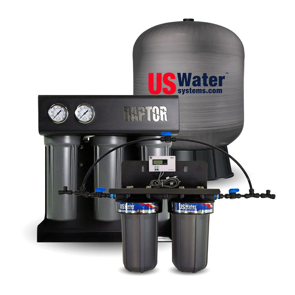
Best for: Food service facilities needing 500–750 GPD of purified water for espresso, ice machines, steam equipment, and food prep — particularly where incoming line pressure is variable or low.
The one absolute rule: TFC membranes tolerate zero free chlorine. Carbon pre-filter maintenance is non-negotiable on municipal water supplies.
Contents
- System overview and what makes it different
- Full technical specifications
- Three-stage pre-filtration — why each stage matters
- Membrane installation and replacement
- Startup procedure and rejection calculation
- Temperature correction for performance monitoring
- Pressurized bladder tank vs. atmospheric tank
- Food service application matrix
- Maintenance schedule
- Troubleshooting
- Warranty — what's covered and what isn't
- FAQ
System Overview: What Makes the Raptor Different
The US Water Systems Raptor bridges the gap between residential RO (50–100 GPD) and full industrial systems. At 500–750 GPD it's sized for applications that exceed residential demand without requiring industrial complexity and cost. Three things set it apart from other light commercial RO systems in this range:
- Integrated booster pump brings operating pressure to 100–125 PSI regardless of incoming supply pressure. Minimum feed required is just 30 PSI — systems with low or inconsistent line pressure work correctly. Most competing systems at this price require adequate feed pressure and produce proportionally less water when pressure is low.
- Dual pressure gauges — feed and product — mounted on the control panel. Most light commercial RO systems ship with no gauges. Having both allows operators to spot membrane degradation (declining product pressure) or supply issues (dropping feed pressure) before water quality is affected.
- 5-year factory warranty on housings, tubing, and fittings. Competing light commercial systems typically offer 1–2 years. This is a meaningful differentiator when specifying a system for a food service installation that needs to run reliably without major capital replacement for several years.
Full Technical Specifications
All specifications from the US Water Systems Raptor RO System Manual, Model 220-USW-RPT-XXX.
| Parameter | 500 GPD | 750 GPD |
|---|---|---|
| Performance | ||
| Permeate flow rate | 0.35 GPM | 0.52 GPM |
| Daily output | 500 GPD | 750 GPD |
| TDS rejection | 97–98.5% (NaCl) | |
| Recovery rate | 50% | |
| Membrane type | Single TFC high-flux | Dual TFC high-flux |
| Operating Limits | ||
| Max feed pressure | 85 PSI | |
| Min feed pressure | 30 PSI | |
| Max operating pressure | 125 PSI | |
| Operating pressure (booster) | 100–125 PSI | |
| Max ambient temperature | 120°F | |
| Min ambient temperature | 40°F — never expose to freezing | |
| Max feed temperature | 85°F | |
| Min feed temperature | 40°F | |
| Feed Water Requirements | ||
| Max turbidity | 1 NTU | |
| Max free chlorine | 0 ppm — zero tolerance | |
| Max TDS | <1,000 ppm | |
| Max hardness | <1 GPG — soften first | |
| Max SDI | <3 | |
| Iron | <0.3 ppm | |
| Manganese | <0.05 ppm | |
| pH range | 3–11 | |
| Physical / Electrical | ||
| Dimensions | 17″ × 12″ × 17″ | |
| Frame | Steel powder-coated, corrosion-proof | |
| Feed/permeate/tank connections | 3/8″ | |
| Concentrate connection | 1/4″ | |
| Power | 120VAC, 60Hz transformer (included) | |
| Configuration | Single-pass | |
| Origin | Made in USA | |
| Rated at 77°F (25°C) and 550 ppm TDS feed water. Performance varies with temperature and feed quality. Source: US Water Systems Raptor RO System Manual. | ||
Three-Stage Pre-Filtration
The Raptor's three pre-filter housings run left to right: sediment (left), GAC carbon (center), catalytic carbon (right). Filter types are not interchangeable between positions — placing the wrong filter in a housing not only reduces effectiveness but can cause membrane failure.
| Stage | Position | Filter Type | Purpose |
|---|---|---|---|
| Stage 1 | Left | 5-micron sediment | Removes particulates, sand, silt — protects downstream stages and membrane from physical fouling |
| Stage 2 | Center | GAC carbon block | Removes bulk chlorine, taste, odor, and organic compounds |
| Stage 3 | Right | Catalytic carbon | Specifically removes chloramine — the form of chlorine used by many municipal utilities that GAC carbon alone does not reliably eliminate |
Filter Installation Procedure
Identify the correct filter for each housing
Left = 5-micron sediment. Center = GAC carbon. Right = catalytic carbon. If there is any risk of confusion, label each filter before removing from packaging.
Remove the sump (housing bowl)
Turn counterclockwise. Work left to right to avoid mixing filter types between housings.
Grease the O-rings
Apply provided O-ring lubricant to both the sump O-ring and the filter O-ring. Dry O-rings cause improper seating and leaks.
Place filter in sump and fully seat
Push the sump with filter up into the filter head until the filter is fully seated. Incomplete seating allows unfiltered water to bypass the filter element — a critical failure mode for the membrane.
Install sump hand tight
Turn clockwise, hand tight only. Do not use a wrench for initial installation — wrench is required later for removal after pressurization.
Membrane Installation and Replacement
New Membrane Installation
Verify 0 PSI on both gauges, system unplugged
Non-negotiable before proceeding.
Remove the membrane cap
Remove the lock clip from the 3/8″ tubing first, then push in on the collet while pulling the tubing — it slides out. Turn the cap counterclockwise.
Open the membrane bag — wear gloves
Do not touch the membrane surface with bare hands. Hand oils and bacteria contaminate the membrane and can cause biological fouling.
Inspect and lubricate
Inspect the brine seal and permeate tube for nicks or cuts — replace if any damage. Lubricate O-rings on the new membrane with the provided lubricant.
Install with brine seal on the cap (feed) side
Critical direction requirement: the brine seal must always face the cap side — the feed side. Reversed installation produces near-zero TDS rejection. The membrane is fully seated when the permeate tube is inset (recessed) from the end of the housing.
Re-install cap and tubing
Turn cap clockwise. Push tubing into collet. Install lock clip. Proceed to startup procedure.
Startup Procedure and Rejection Calculation
Turn on feed water and plug transformer into 110V/60Hz
Use only the included transformer. Do not operate on incompatible power supplies.
Route permeate to drain and monitor TDS
Discard all initial permeate until TDS stabilizes at its minimum value. This flushes the membrane preservative and any sediment from new filters.
Calculate rejection rate before connecting to storage
Minimum acceptable rejection at startup: 96% NaCl. Use the formula below. Do not connect to the storage tank or distribution system until this is confirmed.
Connect permeate line to storage
Once TDS is stable and rejection ≥96%, connect the permeate line to the storage tank or distribution system.
Verify operating pressure
System should run at 100–125 PSI. Pressure varies with feed water temperature and quality. Operating above 100 PSI is required for proper membrane compression and quality water production.
TDS Rejection Calculation
Measure feed water TDS and permeate TDS separately with a TDS meter. Apply this formula:
% Rejection = [(Feed TDS − Product TDS) / Feed TDS] × 100
Example: Feed TDS = 550 ppm, Product TDS = 8.25 ppm → (550 − 8.25) / 550 × 100 = 98.5% rejection.
Temperature Correction for Performance Monitoring
Rated output (500 or 750 GPD) is specified at 77°F (25°C). RO membrane performance is temperature-dependent — water viscosity increases as temperature drops, reducing permeate flow rate. The Raptor manual states 2% of rated output is lost for every degree °F below 77°F.
| Feed Temp | Approx. TCF | Expected Output — 500 GPD system | Expected Output — 750 GPD system |
|---|---|---|---|
| 77°F (25°C) — rated | 1.00 | 500 GPD | 750 GPD |
| 72°F (22°C) | ~0.90 | ~450 GPD | ~675 GPD |
| 65°F (18°C) | ~0.76 | ~380 GPD | ~570 GPD |
| 55°F (13°C) | ~0.58 | ~290 GPD | ~435 GPD |
| 50°F (10°C) | ~0.50 | ~250 GPD | ~375 GPD |
| Approximate values. US Water Systems provides a complete TCF table in 0.5°F increments from 50°F to 85.6°F in the system manual. Actual flow should be within 20% of temperature-corrected rated output — if more than 20% below, suspect membrane fouling or system issues. | |||
Pressurized Bladder Tank vs. Atmospheric Tank
The Raptor is compatible with both storage configurations. The critical operational difference is in the electrical control, not the plumbing:
| Feature | Pressurized Bladder Tank | Atmospheric (Open) Tank |
|---|---|---|
| Pressure switch | Factory-preset 40–60 PSI (included) | Not used — float switch required instead |
| Control | System shuts off automatically at 60 PSI | Float switch prevents overflow and protects pump from dry-running |
| Water delivery | Pressure-fed directly to fixtures | Requires separate distribution pump or gravity feed |
| Best for | Ice makers, plumbed-in faucets, equipment connections | High-volume storage (>50 gallons); large-scale food service with dedicated pump |
Food Service Application Matrix
| Application | Water Quality Need | Raptor Fit | Notes |
|---|---|---|---|
| Espresso and specialty coffee | 75–175 ppm TDS target range | RO foundation — requires blending or remineralization downstream | Pure RO (<10 ppm) produces flat, under-extracted espresso. Post-RO remineralization cartridge or bypass blending required. |
| Commercial ice machines | Scale-free water; clear ice production | Excellent fit | Clearest ROI in food service water treatment — reduces descaling frequency, extends compressor life, produces clear ice. |
| Combi ovens and steam equipment | Scale-free for heat exchanger longevity | Excellent fit | Steam equipment on hard water accumulates scale rapidly. RO-fed steam runs cleaner between service intervals. |
| Brewing and fermentation | Precise mineral profile control | Good fit as base water | RO provides blank-slate water for mineral addition. 500–750 GPD suitable for craft brewery pilot batches and small-format production. |
| Pot fill and general food prep | Consistent quality | Supplemental benefit | Marginal quality improvement over treated municipal water for most cooking. Value is consistency during seasonal municipal variation, not dramatic quality uplift. |
| Aquariums and aquaculture displays | Precise TDS and chemistry control | Good fit | 500 GPD provides adequate output for medium-scale display systems. Remineralization required for freshwater livestock. |
Maintenance Schedule
| Interval | Task | Critical Note |
|---|---|---|
| Weekly | Monitor permeate TDS with a TDS meter | A 20% increase in permeate TDS is the first indicator of membrane damage or fouling |
| Weekly | Observe pressure gauge readings | Declining product pressure = early membrane degradation or fouling signal |
| 6–12 months | Replace all three pre-filters (sediment, GAC, catalytic carbon) | Carbon filter replacement is critical — expired carbon allows chlorine breakthrough to the membrane. Follow filter replacement procedure: unplug, shut off water, both gauges to 0 PSI first. |
| 2–5 years | Replace TFC membrane(s) | Interval depends on feed water quality and usage. Replace sooner if rejection falls below 96% after ruling out fouling, or if permeate flow drops more than 20% below temperature-corrected rated output. |
| As needed | Inspect check valves | Failed check valves allow backflow. Inspect if performance is inconsistent. |
Troubleshooting
| Problem | Likely Cause | Resolution |
|---|---|---|
| Low permeate flow | Cold feed water; clogged pre-filters; low feed pressure; fouled membrane | Apply temperature correction first. Check and replace pre-filters. Verify feed pressure ≥30 PSI. If flow is >20% below TCF-corrected rate, suspect membrane fouling. |
| High permeate TDS (poor rejection) | Chlorine damage; membrane fouling; reversed membrane installation; membrane at end of service life | Verify carbon pre-filters are current. Test feed water for chlorine. If new membrane: verify brine seal orientation (feed side). If established system: clean membrane or replace. |
| System runs continuously (bladder tank install) | Pressure switch set too high; pressure switch failure; low system pressure | Verify pressure switch is set to factory 40–60 PSI. Check operating pressure — system must reach cutoff pressure. Inspect pressure switch. |
| Pump runs continuously (atmospheric tank) | Float switch not installed or failed; tank full but float switch not actuating | Verify float switch is installed and wired correctly. Inspect float mechanism for obstruction. |
| Declining product pressure over weeks | Early membrane scaling or fouling | Check feed water hardness (must be <1 GPG). Inspect pre-filters. If scaling is confirmed, acid cleaning or membrane replacement depending on severity. |
| Permeate TDS >rated but rejection >96% | Feed water TDS above 550 ppm baseline | Normal — rejection percentage is maintained but absolute permeate TDS rises with higher feed TDS. Consider a higher flow rate restrictor if needed. |
Warranty Summary
The Raptor's 5-year warranty on filter housings, membrane housing, tubing, and fittings is significantly longer than competing light commercial RO systems — a genuine differentiator when calculating total cost of ownership over a 5-year commercial installation lifecycle.
| Component | Warranty Period |
|---|---|
| Filter housings, membrane housing, tubing, fittings | 5 years from date of purchase |
| Pumps and electronics | 1 year |
| Filters and membranes (consumables) | Not covered |
FAQ
What TDS rejection does the Raptor achieve?
97–98.5% TDS rejection at 50% recovery, rated at 77°F and 550 ppm feed TDS. Calculate actual rejection as: % Rejection = [(Feed TDS − Product TDS) / Feed TDS] × 100. At a 550 ppm feed, 98.5% rejection produces product water at approximately 8 ppm TDS.
How long is the warranty?
5 years on filter housings, membrane housing, tubing, and fittings. 1 year on pumps and electronics. Filters and membranes are consumables and not covered. The warranty is non-transferable and excludes chlorine damage, freezing, incorrect installation, and operation outside factory specifications.
What feed pressure does the Raptor require?
Minimum 30 PSI. The integrated booster pump brings operating pressure to 100–125 PSI regardless of incoming supply pressure, making the Raptor suitable for low-pressure installations where competing systems struggle. If daytime pressure exceeds 80 PSI, install a pressure reducing valve — nighttime pressure spikes on municipal supplies can otherwise exceed the 125 PSI maximum.
Can the Raptor handle chloramine-treated water?
Yes — Stage 3 is specifically a catalytic carbon filter for chloramine removal. Standard GAC carbon alone does not reliably remove monochloramine at commercial flow rates. Do not substitute a standard GAC filter in the Stage 3 (right) housing position on chloramine-treated municipal water.
Why is my Raptor producing less water than rated?
The most common cause is cold feed water. The 500/750 GPD rating is at 77°F. Approximately 2% of output is lost per degree °F below 77. At 55°F feed water, expect roughly 290/435 GPD — about 58% of rated output. Apply temperature correction before diagnosing a membrane problem. If flow is more than 20% below the temperature-corrected rated output, inspect pre-filters and consider membrane fouling as a cause.