US Water Systems Defender HD Commercial RO Review (2026): 2,000–16,000 GPD Brackish Water
Source: US Water Systems Product Manual 223-DFBROM-XXXX (C. Dietz, 2020) • From $7,195 • Made in USA
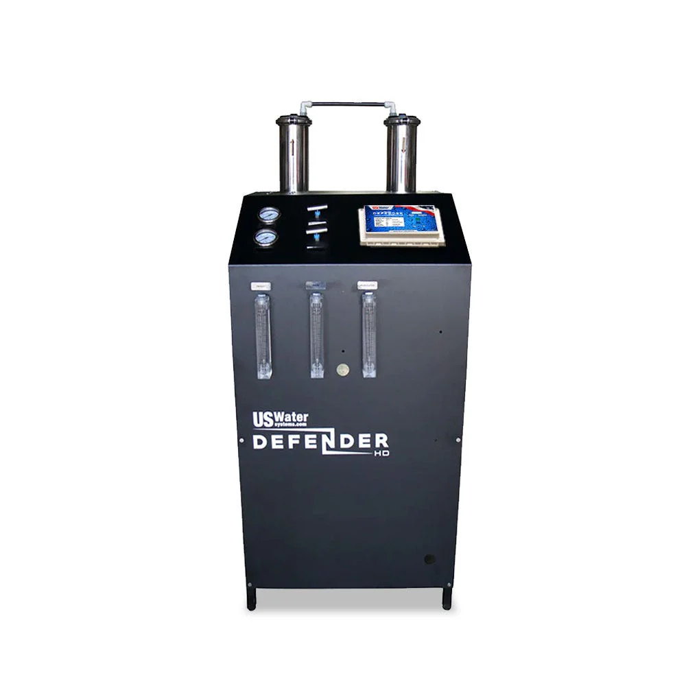
Brackish water RO to 6,000 ppm TDS • 99.5% salt rejection • US100 microprocessor controller • 3 HP multi-stage pump • 2-year warranty
Watch: Defender HD Overview
What Makes the Defender HD Different from Light Commercial RO
Most commercial RO systems — including the Maverick Lite and American Revolution 750 — are designed for municipal water sources with TDS in the 200–500 ppm range. The Defender HD addresses a completely different problem: feed water TDS up to 6,000 ppm from well water, recycled sources, or light industrial supply.
| Feature | Maverick Lite | American Revolution 750 | Defender HD |
|---|---|---|---|
| Output capacity | 200–750 GPD | 750 GPD | 2,000–16,000 GPD |
| Max feed TDS | ~2,000 ppm | ~2,000 ppm | 6,000 ppm (brackish) |
| Salt rejection | 95–98% | 95–98% | 99.5% nominal |
| Controller | Basic | Multi-gauge display | US100 microprocessor |
| From price | $899 | $3,175 | $7,195 |
| Best for | Small commercial, municipal | Light commercial, labs | High-TDS well, industrial, brewing, aquaculture |
Model Configurations & Capacity
All four Defender HD models share the same 26” × 25” × 65” floor footprint, the same US100 controller, and the same 3 HP pump. The difference is in the number of membrane vessels and total membrane area, which determines output capacity.
| Model | Output (GPD) | Output (GPM) | Membrane Vessels | Best Application |
|---|---|---|---|---|
| DFBROM-2000 | 2,000 | ~1.39 GPM | 1 | Small commercial, labs, restaurants on well water |
| DFBROM-4000 | 4,000 | ~2.78 GPM | 2 | Most common selection — medium commercial, brewing, light industrial |
| DFBROM-8000 | 8,000 | ~5.56 GPM | 4 | Large commercial, hospitality, agricultural, car wash |
| DFBROM-16000 | 16,000 | ~11.1 GPM | 8 | Industrial, laundry, manufacturing, municipal supplemental |
| All rated at 77°F (25°C). Apply Temperature Correction Factor for actual cold-water output. For >16,000 GPD: install multiple units in parallel with individual isolating valves. | ||||
Sizing Selection Matrix
| Application | Daily Volume Need | Feed TDS | Recommended Model |
|---|---|---|---|
| Craft brewery (3–10 BBL batches) | 1,000–3,000 GPD | 200–2,000 ppm | DFBROM-2000 or DFBROM-4000 |
| Commercial aquaculture / fish farm | 2,000–6,000 GPD | 500–3,000 ppm | DFBROM-4000 or DFBROM-8000 |
| Cannabis cultivation facility | 3,000–8,000 GPD | 300–1,500 ppm | DFBROM-4000 or DFBROM-8000 |
| Car wash (spot-free rinse) | 4,000–10,000 GPD | 200–800 ppm | DFBROM-4000 to DFBROM-8000 |
| Hotel / hospitality | 5,000–12,000 GPD | 300–2,000 ppm | DFBROM-8000 or DFBROM-16000 |
| Light manufacturing / process water | 8,000–16,000+ GPD | 500–6,000 ppm | DFBROM-8000 or DFBROM-16000 |
Membrane Specifications — 255-US-WEM-4040-225
| Specification | Value |
|---|---|
| Part number | 255-US-WEM-4040-225 |
| Type | Ultra Low Energy 4×40 Polyamide Thin-Film Composite (TFC) |
| Nominal salt rejection | 99.5% |
| Minimum salt rejection | 98.0% |
| Maximum operating pressure | 600 PSI (41 bar) |
| Maximum operating temperature | 113°F / 45°C |
| Chlorine / chloramine tolerance | Zero — polyamide membranes are permanently damaged by any chlorine or chloramine exposure |
| pH operating range | 2–11 |
| Test conditions | 550 ppm TDS, filtered dechlorinated municipal water, 77°F / 25°C, 15% recovery, specified pressure, pH 7.0, 30-min stabilization |
Pre-Treatment Requirements — Not Optional
| Water Challenge | Threshold | Required Pre-Treatment | Controller Integration |
|---|---|---|---|
| Chlorine / chloramine | Any detectable level | Activated carbon filtration (GAC or carbon block) — mandatory | N/A — must be continuously active |
| Hardness (scale risk) | >120 mg/L CaCO₃ | Water softener or anti-scalant injection (Hyper-Guard Plus 7000) | Softener regeneration lockout via pretreatment input |
| Iron | >0.1 mg/L Fe | Iron filter (oxidation + filtration) upstream of carbon and softener | Backwash lockout via pretreatment input |
| Turbidity / sediment | >5 NTU | Sediment filter, 5 micron or finer, upstream of carbon | N/A |
| pH | <4 or >11 | pH adjustment (acid or caustic injection) before membrane | N/A |
| Hydrogen sulfide (H₂S) | Any detectable level | Oxidation and removal before carbon and membrane | N/A |
Anti-Scalant Dosing Reference — Hyper-Guard Plus 7000
When water softening is not practical, anti-scalant injection using Hyper-Guard Plus 7000 provides an effective scale prevention alternative. The dosing pump connects to the US100’s auxiliary “Dosing Pump” outlet and injects proportionally to system operation.
| System Model | Output (GPD) | Initial Tank Fill (Hyper-Guard) | Refill Rate |
|---|---|---|---|
| DFBROM-2000 | 2,000 | 2.5 gallons | 1 oz per 125 gallons permeate |
| DFBROM-4000 | 4,000 | 4.0 gallons | 1 oz per 125 gallons permeate |
| DFBROM-8000 | 8,000 | 7.5 gallons | 1 oz per 125 gallons permeate |
| DFBROM-16000 | 16,000 | 13.0 gallons | 1 oz per 125 gallons permeate |
| Based on 3 GPD chemical injection pump and 15-gallon solution tank. Future refills can use product water from the Defender system itself. Dosing rate assumes typical brackish water hardness — adjust for site-specific water chemistry. | |||
US100 Controller — Complete Reference
The US100 microprocessor controller is what separates the Defender HD from simpler commercial RO systems. It integrates TDS monitoring, pressure fault protection, automatic flush cycles, tank level shutoff, and pretreatment lockout into a single unit — functions that would otherwise require separate instrumentation and controls.
US100 Specifications
| Parameter | Value |
|---|---|
| TDS monitoring | Continuous feed and permeate TDS display |
| TDS alarm setpoint | User-configurable high-TDS shutoff threshold |
| Pressure fault — low inlet | Auto shutoff at <30 PSI inlet pressure |
| Pressure fault — high system | Auto shutoff at >200 PSI system pressure |
| Tank level input | Dry-contact NO float switch (NO voltage — switch contacts only) |
| Pretreatment lockout input | Dry-contact NO switch from softener, filter, or other pretreatment (NO voltage) |
| Dosing pump output | Auxiliary 120V outlet activates with system pump |
| Flush cycle | Programmable automatic flush at startup and shutdown to protect membranes |
| Start delay | 5-second delay after inlet solenoid opens before pump engages (surge protection) |
US100 Display & LED Status Reference
| Display / LED | Status Meaning | Action Required |
|---|---|---|
| System running normally | Feed and permeate TDS displayed; no fault LEDs active | None — record readings for performance log |
| Low inlet pressure fault | Inlet pressure dropped below 30 PSI; system stopped | Check feed supply pressure, supply valve position, pre-filter condition. Do not restart until inlet pressure is stable at 40–60 PSI. |
| High TDS alarm | Permeate TDS exceeded setpoint threshold | Check membrane condition; verify calibration; may indicate membrane failure or bypass |
| Tank full | Float switch triggered; system paused | Normal operation — system will restart automatically when tank level drops |
| Pretreatment lockout | Upstream softener or filter in regeneration/backwash cycle | Normal operation — system will restart automatically when pretreatment returns to service |
| High pressure fault | System pressure exceeded 200 PSI | Stop immediately. Open concentrate valve; reduce pump throttle. Investigate cause before restarting. |
Commissioning — Start-Up Sequence
Open concentrate valve fully (counterclockwise)
Prevents pressure build-up before the system is balanced. Never start the system with the concentrate valve closed or partially closed.
Power on via US100 controller — inlet solenoid opens — 5-second start delay — pump engages
The 5-second delay allows inlet pressure to stabilize before the pump load is applied. Do not power-cycle rapidly during startup.
Run 5–10 minutes to purge air — system may cycle OFF/ON repeatedly — this is normal
Air in filters, tubing, and membrane vessels will cause the system to cycle during initial purge. Allow the purge to complete before adjusting any valves.
Verify inlet pressure 40–60 PSI (30 PSI absolute minimum)
If inlet pressure drops below 30 PSI or fluctuates, stop the system and address the feed supply before continuing. Low inlet pressure is the leading cause of pump damage on startup.
Gradually adjust throttle valve and concentrate valve to target flow rates
Make small adjustments — counterclockwise on throttle to increase pressure; clockwise on concentrate valve to reduce concentrate flow. Wait 2–3 minutes between adjustments for conditions to stabilize. Never exceed 200 PSI.
Discard all permeate for 60 minutes — then verify salt rejection ≥96%
After the flush, read feed TDS and permeate TDS from the US100 display. Salt rejection = (Feed–Permeate)/Feed × 100. Minimum 96% required for warranty compliance.
Performance Formulas — Field Reference
Temperature Correction Factor (TCF) — Quick Reference
All rated GPD figures are at 77°F (25°C). Divide nominal GPM by the TCF at your water temperature to get actual output. Never exceed 200 PSI while compensating for temperature.
| Feed Water Temp (°F) | TCF | Output vs. Rated (%) | DFBROM-4000 Actual GPM |
|---|---|---|---|
| 85.6°F / 30°C | 0.845 | 118% | 3.29 GPM |
| 77°F / 25°C (baseline) | 1.000 | 100% | 2.78 GPM (rated) |
| 68°F / 20°C | 1.189 | 84% | 2.34 GPM |
| 60°F / 15.6°C | 1.424 | 70% | 1.95 GPM |
| 55°F / 12.8°C | 1.541 | 65% | 1.80 GPM |
| 50°F / 10°C | 1.683 | 59% | 1.65 GPM |
| Well water in northern climates commonly runs 45–55°F year-round. Size the system for actual cold-water output, not rated output at 77°F. Source: US Water Systems 223-DFBROM-XXXX manual, pages 37–38. | |||
Membrane Replacement
Membrane efficiency declines gradually. Salt rejection remains stable for 2–3 years on properly pre-treated feed water. Permeate flow may start declining after year one. Cleaning-in-place (CIP) can restore flow performance; it does not restore salt rejection.
Mark brine seal orientation on each vessel BEFORE removing any element
The brine seal (rubber skirt) must be reinstalled in the correct orientation. Mark the vessel and membrane positions before starting — mixing up orientation is the most common installation error.
Remove elements one at a time from the top
Use needle-nose pliers if needed. Do not force elements — damaged brine seals cause bypass and reduced rejection.
Lubricate new brine seals with Silicone DC 111 only (non-petroleum)
Petroleum-based lubricants swell and damage polyamide membrane materials. Use only Silicone DC 111 or equivalent food-grade silicone grease.
Install brine seal side first — slow twisting motion — push until fully seated
A twisted or flipped brine seal allows feed water to bypass the membrane and dramatically reduces salt rejection. Verify the seal is correctly seated before closing the vessel.
Flush new membranes 60 minutes — discard all permeate — verify ≥96% rejection
New membranes contain glycerin preservative. Same flush requirement as initial commissioning.
Troubleshooting Reference
| Symptom | Likely Cause | Resolution |
|---|---|---|
| Salt rejection below 96% | New membranes not fully flushed; membrane failure; O-ring bypass; brine seal installed backward | Continue flushing; inspect O-rings and brine seals; test individual vessels; replace membranes if <96% after 2 hours of flushing |
| Low permeate flow (not cold-water related) | Membrane fouling; pre-filter clogged; inlet pressure low; concentrate valve too open | Check inlet pressure; replace pre-filters; adjust concentrate valve; consider CIP cleaning |
| System cycles OFF/ON repeatedly | Air in system (normal on startup); low inlet pressure; tank full signal cycling | During startup: normal behavior until air purged. If ongoing: verify inlet pressure stability and tank float switch wiring. |
| Inlet pressure drops below 30 PSI under load | Undersized supply line; clogged pre-filter; supply pump undersized | Verify supply line is adequate for 2× the system GPM; replace pre-filters; verify supply source can sustain the flow rate |
| US100 shows high TDS alarm | Membrane failure; O-ring or brine seal bypass; TDS setpoint set too low | Check TDS setpoint; inspect O-rings and seals; test individual vessels; replace membranes |
| System will not start — pretreatment lockout active | Softener or filter in regeneration; wiring issue; normally closed switch used instead of normally open | Verify pretreatment is in service; check wiring uses NO dry-contact switch; wait for pretreatment cycle to complete |
| Rapid scale buildup on membranes | Anti-scalant underdosed; softener bypassing or exhausted; feed TDS higher than expected | Verify anti-scalant dosing rate and solution concentration; test softener effluent hardness; test actual feed TDS |
Warranty Summary
| Component | Warranty Period | Key Conditions |
|---|---|---|
| System components (frame, pump, vessels, controller) | 2 years | Required pre-treatment must be installed and operating; system must be commissioned per manual |
| Membranes | Separate membrane warranty | Salt rejection ≥96% verified at commissioning; pre-treatment operational; no chlorine/chloramine exposure |
| Warranty voids if: | — | No pre-treatment when required; chlorine/chloramine damage; operating above 200 PSI; unauthorized modification; improper installation |
| Warranty service: US Water Systems • 1209 Country Club Road, Indianapolis, IN 46234 • (800) 608-8792 • www.uswatersystems.com | ||
Related US Water Systems Reviews
- US Water Systems Patriot XL — 8,000–16,000 GPD Turnkey Skid-Mounted RO
- US Water Systems Maverick Lite — 200–750 GPD Light Commercial RO
- Raptor Lite Food Service RO — 3,290 GPD Commercial RO
- American Revolution 750 GPD Light Commercial RO
- Brewery Water Treatment Guide — RO Sizing for Craft Breweries
- Agricultural RO Systems Guide
- All Commercial RO Systems